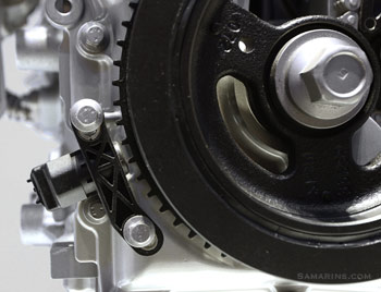
Ford Crankshaft position sensor (CKP)
|
The crankshaft position sensor is the primary sensor of the electronic fuel injection and ignition systems in any modern car. It measures the rotation speed (RPMs) and the precise position of the engine crankshaft. Without a crankshaft position sensor the engine wouldn't start.
The placement of the crankshaft position sensor varies. In some cars, the sensor is installed close to the main pulley (harmonic balancer) like in this Ford in the photo. In other cars, the sensor could be installed at the transmission bell housing, or in the engine cylinder block, as in the photo below. In the technical literature, the crankshaft position sensor is abbreviated to CKP.
The placement of the crankshaft position sensor varies. In some cars, the sensor is installed close to the main pulley (harmonic balancer) like in this Ford in the photo. In other cars, the sensor could be installed at the transmission bell housing, or in the engine cylinder block, as in the photo below. In the technical literature, the crankshaft position sensor is abbreviated to CKP.
How the crankshaft position sensor works
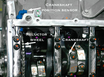
In this GM engine, the crankshaft position
sensor is installed at the cylinder block |
The crankshaft position sensor is positioned so that teeth on the reluctor wheel attached to the crankshaft pass very close to the sensor tip. The reluctor wheel typically has one or more teeth missing to provide the engine computer (PCM) with the reference point to the crankshaft position.
As the crankshaft rotates, the sensor produces a pulsed voltage signal, where each pulse corresponds to the tooth on the reluctor wheel. The photo below shows the actual signal from the crankshaft position sensor with the engine idling. In this vehicle, the reluctor wheel is made with two missing teeth, as you can notice on the graph.
The PCM uses the signal from the crankshaft position sensor to determine at what time to produce a spark and in which cylinder. The signal from the crankshaft position is also used to monitor if any of the cylinders misfires.
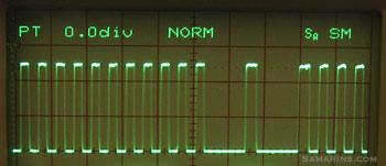
Crankshaft position sensor signal on the oscilloscope screen.
|
If the signal from the sensor is missing, there will be no spark and fuel injectors won't operate.
The two most common types are the magnetic sensors with a pick-up coil that produce A/C voltage and the Hall-effect sensors that produce a digital square wave signal as in the photo above. Most newer cars use the Hall-effect sensors. Typically, a pick-up coil type sensor has a two-pin connector. The Hall-effect sensor has a three-pin connector (reference voltage, ground and signal).
The two most common types are the magnetic sensors with a pick-up coil that produce A/C voltage and the Hall-effect sensors that produce a digital square wave signal as in the photo above. Most newer cars use the Hall-effect sensors. Typically, a pick-up coil type sensor has a two-pin connector. The Hall-effect sensor has a three-pin connector (reference voltage, ground and signal).
Crankshaft position sensor problems
Problems with a crankshaft position sensor are fairly common, especially in older cars. If the sensor is not working properly, a car may stall or not start. The engine will turn over, but won't fire up. Sometimes a failing crankshaft position sensor may cause intermittent issues such as long cranking or stalling in certain conditions, for example, when the engine is hot, or in wet weather. Sometimes a car may stall when hot, but restart after cooled down. In many cars, a failed crankshaft position sensor can also cause a Check Engine light to come on. The most common OBDII code related to the crankshaft position sensor is P0335 - Crankshaft Position Sensor "A" Circuit. In some cars (e.g. Mercedes-Benz, Nissan, Chevy, Hyundai, Kia) this code is often caused by a failed sensor itself, although there could be other reasons, such as wiring or connector issues, damaged reluctor wheel, etc.
How the crankshaft position sensor is tested
Whenever there is a suspicion that the problem might be caused by a crankshaft position sensor or if there is a related trouble code, the sensor must be visually inspected for cracks, loose connector pins or other obvious damage. The proper gap between the tip of the sensor and the reluctor wheel is also very important.
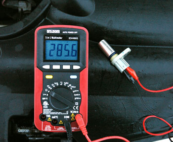
The resistance of this crankshaft position sensor from the 2008 Ford Escape
measures at 285.6 ohms which is within specifications |
The correct testing procedure can be found in the service manual. Typically for the pick-up coil type sensors, the inspection involves checking the resistance. For example, for the 2008 Ford Escape, the resistance of the crankshaft position sensor (CKP) should be between 250-1,000 ohms, according to Autozone. We measured 285.6 ohms (in the photo) which is within specifications. If the resistance is lower or higher than specified, the sensor must be replaced.
For the Hall-type sensors, the reference voltage (typically +5V) and the ground signal must be tested. The most accurate way to test a crankshaft position sensor is checking the sensor signal with an oscilloscope.
Sometimes, the sensor may have an intermittent fault that is not present during testing. In this case checking for Technical Service Bulletins (TSBs) and researching common problems may help. For example, the crankshaft position sensor failure was very common in some early-90's GM cars. One of the symptoms was stalling when the engine is hot. According to many owners at various forums, the new crankshaft position sensor solved the problem.
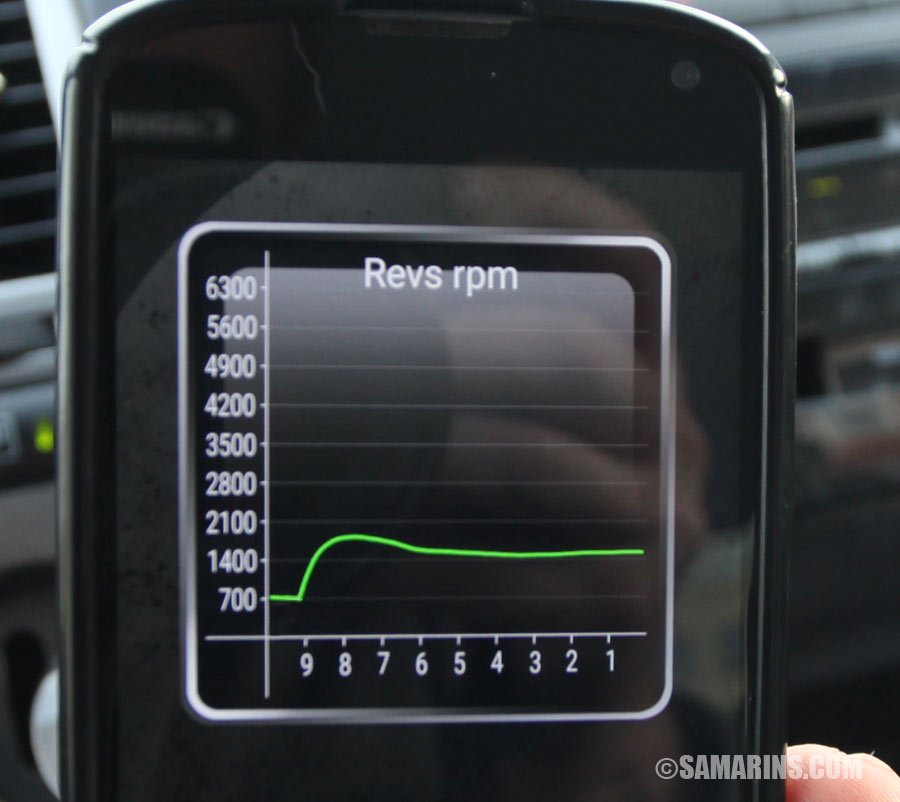
Signal from the crankshaft position sensor is
represented as "Engine RPM" in an OBDII scan tool. |
The crankshaft position sensor can be checked with a scan tool, that shows it as "Engine RPM" or "Engine speed." For example, if the sensor causes intermittent stalling, you might be able to see that when the engine stalls, the RPM signal drops suddenly to zero, as oppose to slowing down gradually. If the RPM signal suddenly drops to zero means that the signal from the crankshaft position sensor is lost. If the sensor works properly, the RPM signal should drop or rise gradually, as in this photo. We have tested this car with an OBDII "Torque" app on the mobile phone.
Crankshaft sensor replacement
Replacing a crankshaft position sensor is not very expensive. The part can cost from $35 to $115 and it's best to use an OEM part. In most cars it's fairly easy to replace, although sometimes the sensor could be difficult to remove due to corrosion.
No comments:
Post a Comment